
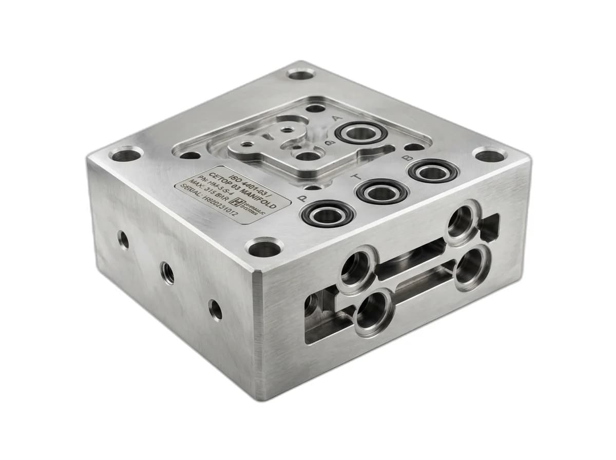
The Three Functional Pillars of Hydraulic Control Valves
In any industrial fluid power circuit, the pump generates flow, but valves dictate pressure, flow direction, and speed. Selecting the improper valve architecture results in severe machine chattering, uncontrolled gravitational load drop, excessive energy dissipation, and high fluid operating temperatures.
Hydraulic valves fall into three distinct functional categories:
- Pressure Control Valves: Regulate maximum system pressure (relief valves), reduce pressure to auxiliary branches (reducing valves), or establish sequence operations.
- Directional Control Valves: Route fluid to advance, hold, or retract actuators via sliding spools or poppet seats.
- Load-Holding & Flow Control Valves: Prevent uncommanded actuator movement under suspended loads (counterbalance and pilot-operated check valves) and govern cylinder linear velocity.
Pressure Relief Valves: Direct-Acting vs Pilot-Operated Mechanisms
The primary pressure relief valve is the supreme safety guardian of every hydraulic circuit. However, choosing between a direct-acting relief valve and a two-stage pilot-operated relief valve dramatically alters system pressure stability under varying pump flow rates:
| Design Feature | Direct-Acting Relief Valve | Pilot-Operated Relief Valve |
|---|---|---|
| Response Speed | Ultra-fast (< 10 ms). Ideal for dampening rapid transient pressure spikes. | Slightly slower (50 to 100 ms) due to two-stage pilot chamber dynamics. |
| Pressure Override | High override. Cracking pressure may be 20% to 30% below full-flow pressure. | Extremely flat override curve (< 5% difference between cracking and full flow). |
| Flow Capacity | Best for low to moderate flow rates (< 40 LPM). High flows require heavy springs. | Handles immense flow rates (up to 400+ LPM) using a compact pilot control stage. |
| Remote Venting | Cannot be remotely unloaded. | Can be vented electrically via a solenoid valve to unload the pump at near-zero pressure. |
In high-tonnage hydraulic press power packs built by Honeywell Hydraulics, pilot-operated relief valves with electric solenoid vent options are standard. This allows the electric motor to start completely unloaded and recirculate oil at near-zero pressure during machine idle intervals, reducing energy consumption and oil heating by over 40%.
Load Holding: Counterbalance (Overcenter) Valves vs Pilot-Operated Check Valves
Holding suspended vertical loads—such as an aerial boom, a freight elevator platen, or a heavy hydraulic press ram—is a safety-critical engineering challenge. Technicians frequently confuse Pilot-Operated (PO) Check Valves with Counterbalance (Overcenter) Valves:
- Pilot-Operated Check Valves (PO Check): These are strictly ON/OFF locking devices. They provide zero-leakage holding when closed. However, when pilot pressure cracks the check poppet open, fluid rushes out instantaneously. If used on a load being pulled down by gravity (overrunning load), the cylinder drops out of control, cavitation occurs behind the piston, pilot pressure drops, the valve slams shut, and violent hydraulic chattering ensues.
- Counterbalance Valves (CBV): These act as modulated, back-pressure regulators. They maintain back-pressure proportional to the external load. As pilot pressure is applied to lower the cylinder, the counterbalance valve opens progressively, meter-outing fluid to ensure the cylinder lowers smoothly at an exact speed dictated by pump flow, regardless of load weight.
Directional Spool Centers: Choosing the Right Neutral Configuration
Standard 4-way, 3-position (4/3) directional control valves feature a neutral center position that dictates circuit behavior when solenoids are de-energized:
- Closed Center (P, T, A, B Blocked - Type E): Locks the cylinder in position while holding pressure in line P. Required for accumulator circuits or systems with multiple parallel valves powered by a variable-displacement pressure-compensated pump.
- Tandem Center (P to T Connected, A & B Blocked - Type G): The most popular configuration for fixed-displacement gear pump power packs. When de-energized, line P unloads freely to the tank at zero pressure while cylinder work ports A and B remain securely hydraulically locked.
- Open Center (P, T, A, B All Connected - Type H): Unloads the pump to tank and vents both cylinder ports to tank. Allows the cylinder to "float" freely under external mechanical manipulation (common in agricultural tillage equipment and road graders).
- Float Center (P Blocked, A & B Connected to T - Type Y): Maintains pump pressure for other circuit branches while venting cylinder ports A and B to tank. Used for motor braking circuits or gravity drop presses.