Why Custom Hydraulic Manifold Blocks Replace Pipe Spaghetti
In traditional hydraulic systems, connecting pumps, directional valves, relief valves, and cylinders with individual threaded pipe fittings and flexible hoses creates an unsightly, space-consuming network known across workshops as "pipe spaghetti." Every threaded joint represents a potential leak point under vibration and pressure spikes.
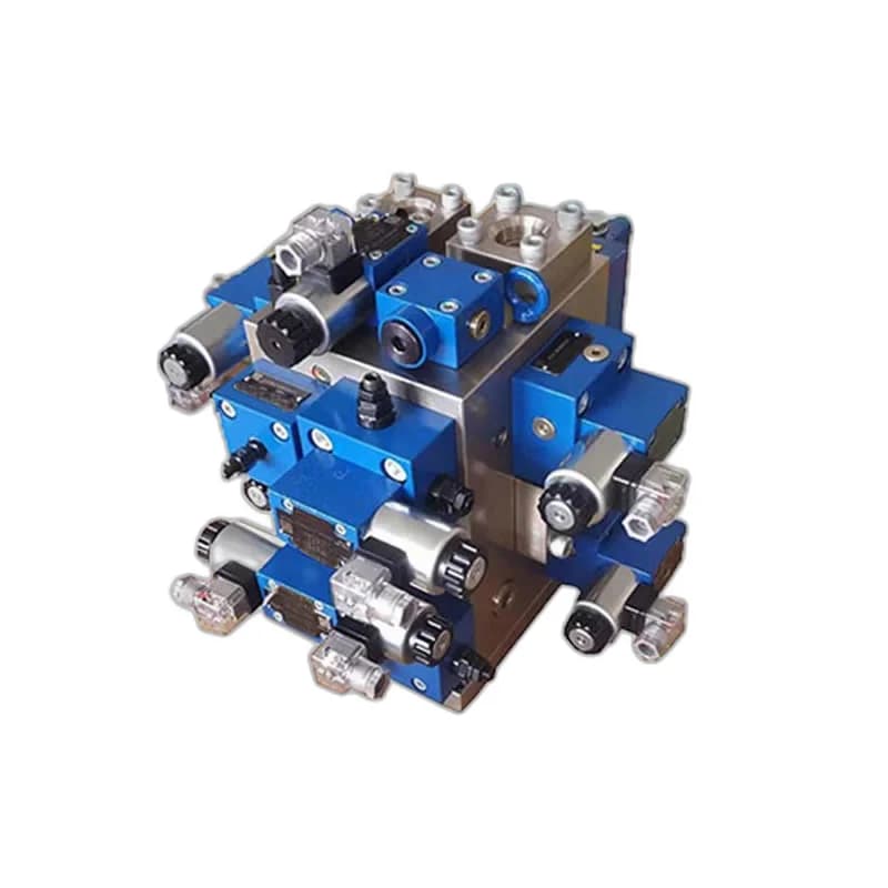
A custom hydraulic manifold block (or integrated hydraulic circuit block) consolidates valves, cartridges, check valves, and pressure controls into a single precision-machined solid metal block. Fluid routes between components through internally drilled galleries, yielding massive engineering advantages:
- Eliminates 90% of External Leak Points: Minimizes hose fittings, threaded elbows, and tees that loosen over time.
- Compact Footprint: Reduces machine envelope size by up to 65%, allowing compact mounting on power pack lids.
- Reduced Pressure Drop: Smooth, optimized internal drillings decrease fluid turbulence and heat generation.
- Simplified Maintenance: Modular CETOP subplate mounting allows valves to be swapped in minutes without unbolting piping.
Standard Mounting Interfaces: CETOP 3 (NG6) vs CETOP 5 (NG10)
To guarantee that directional control valves from any global manufacturer (such as Rexroth, Vickers, Yuken, or Polyhydron) mount interchangeably, manifold mounting surfaces adhere strictly to international standard ISO 4401 (NFPA / ANSI B93.7M / CETOP):
| Standard Designation | Nominal Size | Bolt Pattern Dimensions | Mounting Fasteners | Max Flow Capacity |
|---|---|---|---|---|
| CETOP 3 / D03 / NG6 (ISO 4401-03) | 6 mm nominal | 40.5 mm × 31.0 mm (4-bolt pattern) | 4 × M5 screws (Grade 12.9) | Up to 60–80 LPM |
| CETOP 5 / D05 / NG10 (ISO 4401-05) | 10 mm nominal | 54.0 mm × 46.0 mm (4-bolt pattern) | 4 × M6 screws (Grade 12.9) | Up to 120–160 LPM |
| CETOP 7 / D07 / NG16 (ISO 4401-07) | 16 mm nominal | 88.9 mm × 76.2 mm (6-bolt pattern) | 4 × M10 + 2 × M6 screws | Up to 300 LPM |
| CETOP 8 / D08 / NG25 (ISO 4401-08) | 25 mm nominal | 130.2 mm × 114.3 mm (6-bolt pattern) | 6 × M12 screws | Up to 650 LPM |
At Honeywell Hydraulics, all CETOP 03 and CETOP 05 multi-station subplates are CNC machined with locating pin holes per ISO 4401 to prevent inverted valve installation.
Material Selection: Aluminum vs Ductile Iron vs Carbon Steel
Selecting the correct raw block material depends on operating pressure, cyclic pressure fatigue, and machine duty cycle:
- 6061-T6 Aircraft Grade Aluminum:
Pressure Rating: Up to 210 Bar (3,000 PSI)
Excellent machinability, low weight (one-third the weight of steel), and inherent corrosion resistance. Ideal for mobile cranes, access platforms, and general industrial automation up to 210 Bar. - Continuous Cast Ductile Iron (EN-GJS-400 / 500):
Pressure Rating: Up to 350 Bar (5,000 PSI)
Ductile iron provides superior fatigue resistance against high cyclic pressure impulses without micro-cracking. It is the gold standard material for industrial hydraulic presses and injection moulding machines. - C45 / Carbon Steel / Stainless Steel:
Pressure Rating: 420 to 700 Bar (6,000 to 10,000 PSI)
Specified for ultra-high-pressure jacking systems, offshore oil & gas, marine environments, and food-grade washdown applications requiring 316L stainless steel.
Internal Gallery Design & Flow Velocity Limits
Drilling internal channels requires careful calculation of fluid velocity to prevent localized cavitation, noise, and pressure drop. Fluid velocity inside manifold chambers should adhere to these thresholds:
- Pressure Galleries (P): Maximum 5.0 to 6.0 m/s
- Work Ports (A and B): Maximum 4.0 to 5.0 m/s
- Tank Return Galleries (T): Maximum 2.0 to 3.0 m/s (Tank lines must be 25–40% larger than pressure lines to accommodate differential cylinder return flow)
Minimum Wall Thickness Safety Rule: The metal wall between two pressurized intersecting drillings must never be less than 3.0 mm for aluminum and 2.5 mm for ductile iron / steel. Inadequate web thickness between cross-drilled passages can burst internally, causing undetectable circuit bypass.
Surface Finish, O-Ring Grooves & Cavity Machining
A manifold block's sealing integrity depends entirely on the micro-finish of its valve interface faces. Standard commercial milling (Ra 1.6–3.2 µm) is completely inadequate and will leak under continuous pressure.
Honeywell Hydraulics machining guidelines require:
- Mounting Surface Finish: Ground or fly-cut to Ra ≤ 0.4 µm (16 µin) with a surface flatness within 0.01 mm over 100 mm span.
- O-Ring Counterbores: Machined using dedicated CNC form tools to ensure precise depth and 0.2 mm corner radii, eliminating seal extrusion under 350 Bar pressure spikes.
- Cross-Hole Deburring & Ultrasonic Cleaning: All internal passage intersections must be deburred using thermal or orbital abrasive techniques, followed by multi-stage ultrasonic washing to eliminate loose metal chips before assembly.
Checklist for Custom Manifold Block Manufacturing
When sending a manifold block drawing or circuit schematic to Honeywell Hydraulics for custom CNC manufacturing, provide the following specifications:
- ☐ Complete hydraulic circuit schematic (ISO 1219 symbols)
- ☐ Valve interface sizes: CETOP 3 (NG6), CETOP 5 (NG10), or cartridge cavity standards (e.g., Sun Hydraulics / HydraForce)
- ☐ Maximum continuous operating pressure and peak surge pressure (Bar)
- ☐ Total system pump flow (LPM) and actuator flow demands
- ☐ Preferred material: 6061-T6 Aluminum, Ductile Iron, or Steel
- ☐ Port connection types: BSPP (ISO 1179), Metric (ISO 6149), or SAE O-ring boss (ISO 11926)
- ☐ Special surface coatings: Black anodizing (aluminum), zinc electroplating, or chemical blackening (steel)
Our engineering design team utilizes dedicated 3D hydraulic manifold CAD software to optimize drill runs, eliminate blind plugs, and simulate pressure drop prior to 5-axis CNC machining.