
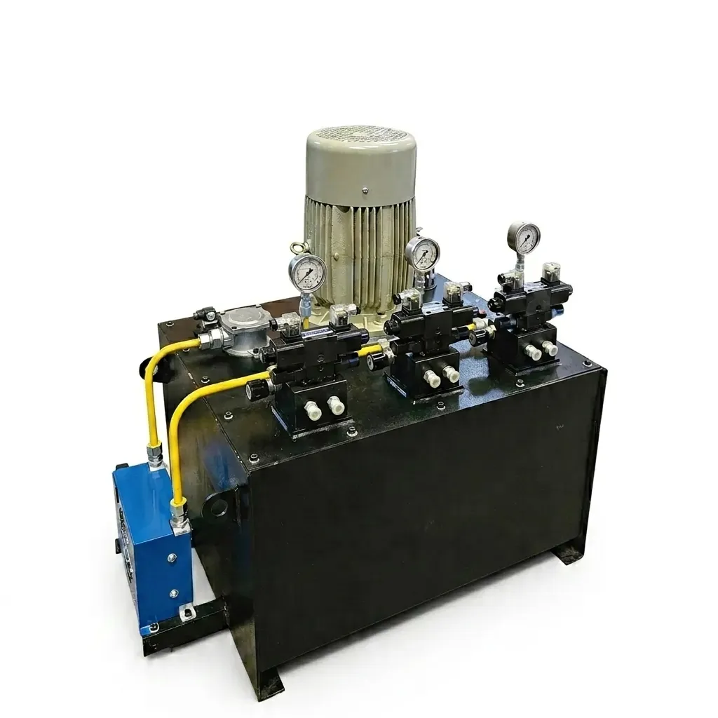
Understanding Hydraulic Power Unit (HPU) Architecture
A hydraulic power pack (also known as a Hydraulic Power Unit or HPU) is the mechanical heart of any fluid power circuit. It converts electrical energy into controlled hydraulic fluid pressure and flow to drive cylinders, hydraulic motors, and actuators across plastic injection moulding machines, scrap balers, material handling lifts, and hydraulic presses.
An incorrectly sized power pack introduces severe operational bottlenecks: an undersized motor overheats, trips circuit breakers, and stalls under peak tonnage; an undersized pump produces sluggish cycle times; while an undersized reservoir causes fluid aeration, rapid oil degradation, and thermal runaway. Conversely, oversizing drastically escalates initial capital expenditure and electricity consumption.
This engineering guide outlines the precise calculation sequence executed by Honeywell Hydraulics design engineers at our Ahmedabad facility when engineering custom hydraulic power units for OEMs and SPM builders across India.
Step 1: Calculate Required Pump Flow Rate (Q)
The first parameter required is the oil flow rate (Q, in Litres Per Minute). Pump flow is dictated entirely by actuator displacement volume and the machine's target operating speed.
For hydraulic cylinders, required flow is calculated by multiplying effective piston area (A) by the target linear rod velocity (v):
- Q = Required pump delivery in Litres per Minute (LPM)
- A = Piston area (cm²). Push area = π/4 × D²; Pull area = π/4 × (D² − d²)
- v = Target cylinder speed (cm/second)
- 16.67 = Unit conversion constant (cm³/s to L/min)
Industrial Example: A 160 mm bore cylinder (201.06 cm² area) on a hydraulic press approach stroke needs to travel at 8 cm/s:
Q = (201.06 cm² × 8 cm/s) ÷ 16.67 = 96.48 LPM
Factoring in volumetric pump efficiency (typically 90% to 92% for positive-displacement external gear pumps), the required theoretical pump displacement is selected as 105 LPM.
Step 2: Calculate Electric Motor Power (kW & HP)
Once required flow and maximum system operating pressure are defined, the electric motor rating can be calculated using the fundamental fluid power relationship:
Where:
- P (kW) = Electric motor shaft power in kilowatts
- Q = Pump flow delivery in Litres per Minute (LPM)
- p = Maximum circuit relief pressure setting in Bar
- 600 = Standard metric conversion constant (1 Bar = 100 kPa; 1 LPM = 1/60 dm³/s)
- ηt = Total mechanical-hydraulic system efficiency (typically 0.82 to 0.88 for gear pumps, 0.88 to 0.92 for piston pumps)
Example: Sizing a motor for 60 LPM at 210 Bar working pressure with a total efficiency of 0.85:
- Hydraulic Power = (60 × 210) ÷ 600 = 21.0 kW
- Shaft Power with Efficiency = 21.0 ÷ 0.85 = 24.7 kW
- Standard IEC Motor Selection: Next standard motor frame is 30 kW (40 HP), 4-pole, 1440 RPM induction motor.
Motor Sizing Quick Reference Table (at 1440 RPM)
The table below provides recommended electric motor sizes for common flow rates and operating pressures using external gear and vane pump configurations (assuming ηt = 0.85):
| Flow Rate (LPM) | Motor at 100 Bar | Motor at 160 Bar | Motor at 210 Bar | Motor at 250 Bar |
|---|---|---|---|---|
| 10 LPM | 2.2 kW (3 HP) | 3.7 kW (5 HP) | 5.5 kW (7.5 HP) | 5.5 kW (7.5 HP) |
| 20 LPM | 4.0 kW (5.5 HP) | 7.5 kW (10 HP) | 9.3 kW (12.5 HP) | 11.0 kW (15 HP) |
| 35 LPM | 7.5 kW (10 HP) | 11.0 kW (15 HP) | 15.0 kW (20 HP) | 18.5 kW (25 HP) |
| 50 LPM | 11.0 kW (15 HP) | 15.0 kW (20 HP) | 22.0 kW (30 HP) | 30.0 kW (40 HP) |
| 75 LPM | 15.0 kW (20 HP) | 22.0 kW (30 HP) | 30.0 kW (40 HP) | 37.0 kW (50 HP) |
| 100 LPM | 22.0 kW (30 HP) | 30.0 kW (40 HP) | 45.0 kW (60 HP) | 55.0 kW (75 HP) |
| 150 LPM | 30.0 kW (40 HP) | 45.0 kW (60 HP) | 55.0 kW (75 HP) | 75.0 kW (100 HP) |
Honeywell Hydraulics manufactures both single-phase (up to 3.7 kW) and heavy-duty three-phase (up to 110 kW) hydraulic power packs with custom motor mounts.
Step 3: Oil Reservoir Tank Capacity Sizing
The hydraulic oil tank does far more than store hydraulic oil. It performs four mission-critical engineering functions: dissipation of generated frictional heat, release of entrained air bubbles, settlement of heavy particulate contaminants, and accommodation of thermal expansion and differential actuator volume.
The standard industrial rule for sizing industrial stationary hydraulic power unit reservoirs is:
- Standard Industrial Rule: Tank Volume = 3 to 5 times pump delivery per minute. For a 40 LPM pump, tank capacity should be 120 to 200 Litres.
- Severe Duty & Continuous Cycling: Tank Volume = 5 to 8 times pump delivery (or install forced air/water oil coolers).
- Mobile / Compact Packs: Tank Volume = 1.5 to 2 times pump delivery (mandatory requirement for external heat exchangers).
Additionally, reservoir engineering must include an interior longitudinal baffle plate dividing the suction and return chambers. The baffle prevents turbulent fluid returning from the relief valve from being immediately sucked back into the pump, ensuring adequate cooling and de-aeration time.
High-Low Pump Circuits: Cutting Motor Horsepower in Half
In machinery with distinct rapid-traverse approach cycles followed by high-tonnage slow pressing (such as sheet metal stamping, scrap balers, and coining presses), using a single large pump operating at high pressure requires an unnecessarily massive electric motor.
A High-Low (Hi-Lo) hydraulic circuit solves this by pairing two pumps driven by a single motor:
- High-Flow, Low-Pressure Pump: Provides rapid cylinder extension at low pressure (e.g., 20–40 Bar).
- Low-Flow, High-Pressure Pump: Provides final pressing tonnage at full pressure (e.g., 210–350 Bar).
- Unloading Valve: When the cylinder touches the workpiece and pressure builds, the large pump unloads back to tank at near-zero pressure, leaving the smaller pump to generate high clamp tonnage.
Energy Saving Impact: A conventional circuit requiring a 37 kW (50 HP) motor can frequently be powered by a 15 kW (20 HP) motor using a Honeywell Hydraulics Hi-Lo manifold circuit, reducing electricity consumption by up to 60%.
Step 4: Hydraulic Pipe & Hose Velocity Limits
Fluid friction in undersized hydraulic hoses and pipe runs generates excessive heat, causes severe pressure drop, and induces pump cavitation. Piping must be sized to keep fluid velocity (v) within strict empirical limits:
| Line Type | Recommended Fluid Velocity | Impact of Undersizing |
|---|---|---|
| Suction Line (Tank to Pump) | 0.6 to 1.2 m/s (2 to 4 ft/s) | Pump inlet cavitation, severe noise, gear/vane erosion |
| Pressure Line (< 210 Bar) | 3.0 to 5.0 m/s (10 to 16 ft/s) | Excessive pipe friction, fluid heating, pressure loss |
| High-Pressure Line (> 210 Bar) | 4.5 to 6.5 m/s (15 to 21 ft/s) | Pressure spikes, hydraulic shock, reduced seal life |
| Return Line (Valves to Tank) | 1.5 to 3.0 m/s (5 to 10 ft/s) | High back-pressure on valve tank ports, seal blowout |
Engineering Checklist for Custom Power Pack RFQ
When requesting an engineering design quote from Honeywell Hydraulics, gather the following system parameters:
- ☐ Target operating pressure (Bar / PSI) and peak relief valve setting
- ☐ Number of actuators (cylinders, hydraulic motors, rotary indexers)
- ☐ Required cycle speed and individual stroke times
- ☐ Continuous duty cycle (hours per day, ambient plant temperature)
- ☐ Valve control methodology: Manual levers, solenoid 24VDC / 220VAC, or proportional control
- ☐ Environmental constraints: Indoor, outdoor, dusty, marine, or explosive atmosphere
- ☐ Oil filtration requirement (typically 10-micron return, 25-micron suction strainer)
Submit your parameters to our engineering team for full 3D CAD modeling, component selection, and quotation within 24 hours.